Plate Bending Trajectories
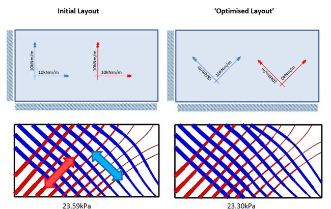
For plate bending problems, principal moment trajectories may be used to define a reinforcement layout. The following figure shows principal moment trajectories for a reinforced concrete slab uniformly loaded and simply supported on two adjacent sides. The left column shows the trajectories at collapse for the case of uniform isotropic reinforcement. The load to cause collapse is 23.59kPa. The right column shows the trajectories when the reinforcement is rotated through 45 degrees and with one direction removed from both hogging and sagging layers. The collapse load is reduced very slightly to 23.30kPa but there is a massive (50%) saving in reinforcement.